*** Disclaimer ***
This information is provided for entertainment purposes only. You acknowlege, by use of this site, that your use of this site is a your sole risk.
Information on this site may not constitute the most up-to-date engineering or other technical information. This website contains links to third-party websites. Such links are only for the convience of the reader, user or browser; we do not recommend or endorse the contents of third-party sites.
MathCAD Design Calculations for a Ring Stiffened Cylinder of the submarine “Delta” :
(click to open the PDF)
General note regarding models: A particular model is predicating a particular failure mode. If the predicted depth is greater than another model, it doesn't mean the value is wrong, it just means that the lower depth failure mode would occur first and therefore the greater depth failure mode would not occur. Essentially the lowest predicated value is the expected failure depth.
Shell Calculations:
Simple Hoop Stress -- Shell Yield using the Simple Hoop Stress Formula - Marks, Lionel S."Mechanical Engineering Handbook, Fifth Edition, 1951, Page 421
This provides the theoretical maximum depth a perfect circular shell can withstand until it yields and collapses. A thicker shell will increase the depth. A larger OD will decrease the depth.
Shell Thickness = 0.5" OD = 42", Failure Depth = 2036 ft. sea water
Shell Collapse by General Instability -- Shell Collapse by General Instability using Kendricks Equation as modified by Bryant - Comstock, John Paul, "Principles of Naval Architecture, 1967
p. 213, Equation[33]
This simulates the number of lobes for failure. The minimum value should be used to determine the collapse depth and will show the number of lobes for failure. The shell thickness and outside diameter are varied to show the affect on the depth of failure. The predicted depth of failure is much greater than predicted by the simple hoop stress which indicates that failure by General Instability is not the predicted failure mode.
Shell Thickness = 0.5" OD = 42", Failure Depth = 7133, 7105 ft. sea water
Elastic Shell Buckling -- Elastic Shell Buckling using Non-Dimensional Analysis - Comstock, John Paul,"Principles of Naval Architecture", 1967, Page 208
A thicker shell will increase the depth. A larger OD will decrease the depth.
Shell Thickness = 0.5" OD = 42", Failure Depth = 2892 ft. sea water
Bodily Collapse -- Bodily Collapse using Tokugawa's Equation - Trilling, Charles"The Influence of Stiffening Rings on the Strength of Thin Cylindrical Shells Under External Pressure", U.S. Experimental Model Basin Report No. 396 February 1935, p. 7, Equation [10]
A thicker shell will increase the depth. A larger OD will decrease the depth. The predicted depth of failure is much greater than predicted by the simple hoop stress which indicates that failure by Shell Buckling is not the predicted failure mode.
Shell Thickness = 0.5" OD = 42", Failure Depth = 4616 ft. sea water
Shell Buckling Von Mises -- Shell Buckling using Von Mises Equation - Widenberg, D.F and Trilling, C."Collapse by Instability of a Thin Cylindrical Shells Under External Pressure" ASME Trans, Volume 56, 1934, P. 820, Equation [6]
This simulates the number of lobes for failure. The minimum value should be used to determine the collapse depth and will show the number of lobes for failure. The shell thickness and outside diameter are varied to show the affect on the depth of failure. A thicker shell will increase the depth. A larger OD will decrease the depth. The predicted depth of failure is much greater than predicted by the simple hoop stress which indicates that failure by Shell Buckling is not the predicted failure mode.
Shell Thickness = 0.5" OD = 42", Failure Depth = 3051 ft. sea water
Shell Buckling Widenberg -- Shell Buckling using Widenberg's Formula - Comstock, John Paul,"Principles of Naval Architecture", 1967, Page 209, Equation [19]
A thicker shell will increase the depth. A larger OD will decrease the depth.
Shell Thickness = 0.5" OD = 42", Failure Depth = 3102 ft. sea water
Shell Yield Von Sanden and Gunther -- Shell Yield using Von Sanden and Gunther's Equation - Comstock, John Paul "Principles of Naval Architecture", 1967, p. 210, Equation [21]
This predicts the depth to failure at the Frame (the Ring) and Mid-Bay. The lower of the two values is the predicted failure depth and failure mode. A thicker shell will increase the depth. A larger OD will decrease the depth.
Shell Thickness = 0.5" OD = 42", Failure Depth = 1846 ft. sea water, Failure at the Frame.
Ring Calculations:
Ring Collapse -- Ring Collapse using Formula (88) - Trilling, Charles"The Influence of Stiffening Rings on the Strength of Thin Cylindrical Shells Under External Pressure", U.S. Experimental Model Basin Report No. 396
February 1935, p. 6, Equation [8]
Ring Web Thickness = Ring Flange Thickness = 0.5" , Ring Width = 2", Ring Depth = 2.5" Failure Depth = 4477 ft. sea water
The rings are stronger than the main shell.
Ring Hoop Stress -- Ring Yield using Frame Hoop Stress - Comstock, John Paul"Principles of Naval Architecture", 1967, p. 211, Equation [27]
Ring Web Thickness = Ring Flange Thickness = 0.5" , Ring Width = 2", Ring Depth = 2.5" Failure Depth = 24,867 ft. sea water
The rings are much stronger than the main shell.
Ring/Shell Yield -- Ring Study of Shell Yield using Von Sanden and Gunther's Equation - Comstock, John Paul"Principles of Naval Architecture", 1967, p. 210, Equation [21]
The Ring width is varied to see the affect. A thicker ring decreases the depth as expected. Having a stiffer ring caused the shell to bend at the ring decreasing the depth.
Ring Web Thickness = Ring Flange Thickness = 0.5" , Ring Width = 2", Ring Depth = 2.5" Failure Depth = 2061 ft. sea water mid-bay, 1816 ft. sea water at the frame.
So the ring is slightly too strong, but using the same material thickness 0.5" for the shell and the ring overrode this small difference.
Weight and Displacement Calculations:
Weight and Displacement -- Weight and Displacement of a Ring Stiffened Cylinder: This does not include the Volume and Weight of the Conning Tower or Battery Box
The predicted payload is 3205 lbs. More than enough for personnel and equipment, but added lead ballast will be needed.
Port Calculations:
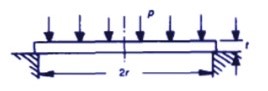
Port Yield and Deflection -- Circular plate, uniform load, edges simply supported.
Port Material: Grade G Plexiglass
Tensile Strength, maximum 10,500 psi
Tensile Strength, yield 10,500 psi
Tensile Elongation 4.9 %
Tensile Modulus of Elasticity 450,000 psi
Poisson’s Ratio 0.35
Flexural Strength, maximum 16,000 psi
Flexural Modulus of Elasticity 450,000 psi
Notched Izod Impact @ 73°F (23°C) 0.3 ft-lb / in
Un-Notched Charpy @ 73°F (23°C) 7.0 ft-lb / 0.5”x1” section
The deflection at the center of the port is only 28 thousandths of an inch at the at a depth of 1320 ft. of seawater.
Testing to verify design calculations:
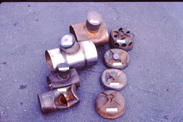
Several scale models were made and tested to destruction to verify the calculated design depth. It was somewhat with a heavy heart when we put them into the pressure chamber to crush them, since one had taken us over two months to make, within 0.001” tolerance on the dimensions (as close as we could make/measure it).
Crush depth of each model (respectively):
2793 ft. 2838 ft.
2763 ft. 3086 ft.
2882 ft. 2725 ft.
3041 ft. 3625 ft.
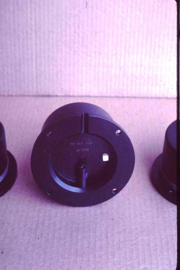
The internal rings were made as a “T” to increase the stiffness and decrease the ring weight.
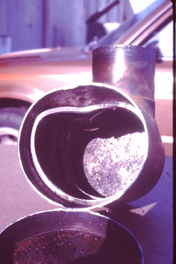
When first tested the model failure occurred at 2763 ft and 2793 ft. (fairly close). The failure occurred on the main cylinder where the conning tower connects. This seemed to be a one lobe failure.
Since the front and back portions of the model were still intact, the front and back semi-elliptical heads were sawn off and tested to see what their failure depth would be. The front head section with all the ports failed at 2838 ft. only 100 ft. deeper than the hull (again fairly close). The rear head containing the motor compartment failed at 3086 ft. and 2725 ft. (again fairly close) but greater than the main head. The strongest model was front head section with no ports failing at 3625 ft. These seemed to be a general instability failure.
The calculated failure depth using the Simple Hoop Stress formula is 2036 ft. This should be the theoretical maximum of a basic shell, but additional stiffening (braces and rings) could increase this.
The calculated failure depth using the Von Sanden and Gunther formula is 2061 ft. at Mid-Bay
Both of these predictions are fairly close to the actual model failure depths, however the actual failure was 35% and 34% respectively higher than predicted. This could have been due to using material with an increased yield strength in the construction the model or increased thickness. We used certified material for the models which showed it’s tested yield strength, but I used the minimum Yield Strength value for the A515 Grade 70 Pressure Vessel Grade Steel for the calculations, any additional strength would only increase the margin of safety. Plus, we had tried to hold everything to within 0.001” (the closest we could measure and make).
A515 Pressure Vessel Grade Steel Mechanical Properties
|
Grade |
60 [415] |
65 [450] |
70 [485] |
Tensile strength, ksi [MPa] |
60-80 [415-550] |
65-85 [450-585] |
70-90 [485-620] |
Yield strength, min, ksi[MPa] |
32 [220] |
35 [240] |
38 [260] |
Elongation in 8 in. [200 mm], min, % * |
21 |
19 |
17 |
Elongation in 2 in. [50 mm], min, % * |
25 |
23 |
21 |
* See Specification A20/A20M for elongation adjustment.
This gave us good confidence that the “Delta” would not fail under normal operation. We designed it to 2640 ft. which provided a 2 : 1 safety factor and tested the actual sub to 1920 ft which provided 1.5 : 1 safety factor. So by only diving to a maximum of 1320 ft., we would never get close to yield in actual use.
The designed maximum depth is 1320 ft, but the American Bureau of Shipping (ABS) certified “Delta” to 1200 ft. and reduced the rated depth due to the low temperature characteristics of A515 and restricted the water temperature that “Delta” could dive in. It turned out we should have used A516 Pressure Vessel Grade Steel, which has better low temperature properties and we would not have had a low water temperature restriction.
“Delta” was marked with a A1 on the right side ring to indicate it was not built under ABS survey. If it had been built under ABS Survey it would have been marked with ✠ A1 .
ABS: Rules for Building and Classing Underwater Vehicles, Systems and Hyperbaric Facilities 2021
Communications
For underwater communications we used a single side-band (Upper side-band) 8.087KHz carrier, 3KHz Voice bandwith acoustic "radio". This was chosen because it is compatible with the U.S. Navy's (a likely rescurer) Underwater Telephone.
UQC_Underwater_Communications_Unit_Schematic
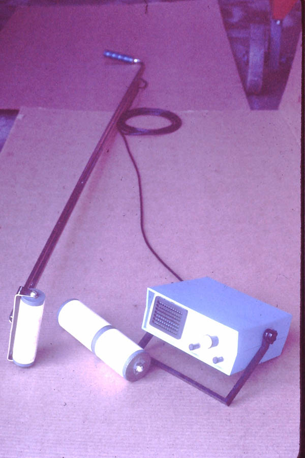
A custom designed Piezoelectric transducer is used for both transmission and reception. It's reasonance frequency is 9587 Hz which is in the middle of the upper side-band 3KHz voice band.
A second version was built with a 28,500 Hz. tranceiver placed on top (the smaller one in the picture below). This transducer was never used.
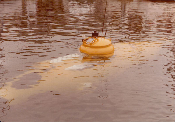
For surface communications we used marine band radio (the short antenna above) and Citizens Band (the long antenna above) radios. The antennas are on the top of the hatch and work until the submarine submerges. Pre-designated channels are set for both the submarine and support vessel.
Submarine Location
On the submarine a Pinger (the white cylinder next to the top port in the pictuer above) is used to emit an ultrasonic 10ms pulse once per second at 37 kHz. This is the same frequency used by aviation flight recorders, so there is plenty of equipment that can be used to find the submarine as long as it is transmitting. It is automatically turned on when immursed in sea water (which is conductive) which acts as the On/Off switch. On the support vessel an acoustic direction finder (tuneable from 5KHz to 50KHz) is used to determine the direction towards the submarine when submerged.
The submersible is tracked from the support vessel using a combination of an ORE Trackpoint II Ultra-Short Baseline (USBL) acoustic system, an SG Brown meridian
standard gyrocompass, WINFROG (v. 3.1, Fugro, San Diego, California) software, and a Furuno Navigator GP-36 differential global positioning system (GPS).
Life Support
Your body uses Oxygen out of the air (naturally 21%) when you breath. When you close the hatch you have created a finite amount of air for you to breathe. To replensh Oxygen as it is removed by your body, an Oxygen bottle (Blue bottle) inside the submarine is provided to supply your Oxygen for the mission. An adjustable flow meter is provide to regulate how much Oxygen is flowing into the submarine (set to 2 cu. ft. per hour, which is enough for two passengers). When the hatch is closed an airplane Altimeter is set to Zero ft. of altitude. During the mission if the altitude goes up, this means that not enough Oxygen is flowing, if the altitude goes down, too much Oxygen is flowing. This is indicator is very IMPORTANT! to monitor if you are not bleeding enough Oxygen in you can pass out without knowing it. An Oxygen sensor is provide to indicate the percentage of Oxygen and also create an alarm when it is too low. A three day supply of Oxygen is also stored outside the submarine in the rear ballast tank in two Oxygen bottles. This is the Emergency Supply and is not used. Pressure gauges provide an indication of how much Oxygen remains in the bottles.
Your body naturally generates Carbon Dioxde when you breath. Too much Carbon Dioxide can be fatal, fortunately your body can sense a build up of Carbon Dioxide, it gets stuffy. Carbon Dioxide is removed from the submarines internal air with SodaSorb, by simply running the air over it. A canister and blower move the air over the SodaSorb (it is controlled by a switch since it is rather noisy). This cannister contains enough for a full day of underwater operation and is replaced with fresh SodaSorb before the first dive of the day. Fourteen sealed bottles of SodaSorb provide a three day Emergency Supply, these are in racks behind the pilot on eachside of the submarine.
Three days Emergency Supply of Oxygen and Carbon Dioxide scrubber was determined to allow for: 1) one day to get stuck, 2) one day for rescue tteam to arrive and 3) one day for the rescurers to get you back to the surface. This is a minimum, you also have a partial mission supply, which could provide up to an additional day, but that depends on when you get stuck (in the morning on the first dive or in the evening on the last dive of the day).
Elecrical Power
Power is supplied by eight 244 AHr 6V DC deep cycling lead acid batteries providing 11.7KWhr of power. This is sufficient to operate the submarine for an entire day. At the end of the day the batteries are charged, however during charging it breaks down the water into Hydrogen and Oxygen in the perfect mixture for and explosion. Hydro-Caps are installed to convert the Hydrogen and Oxygen back into water which drains back into the battery. Also, the battery boxes can be purged (to remove any Hydrogen and Oxygen in the boxes) with compessed air while on the surface. Valves are provided for exhaust and values to release SCUBA compressed air into each separate battery box.
The batteries are installed into two separate battery boxes (four batteries each) and wired in series. One bank provides 12V and 24V taps, the second bank is only 24V. Three Main Circuit breakers (one 12V anxd two 24V) are installed to turn off the power in the event of a short circuit. 12V and 24V power is provided for lights and instrumentation inside the submarine. A switch runs either 24V or 48V to the motor, the two banks in parallel or in series. A reversing switch is used for forward and reverse thrust form the propeller (the motor runs clockwire or counter-clockwise).
During the certification process we came to an impasse with the ABS. Their rules mandated that an ungrounded electrical system be used. We analyzed this and determined that their regulation was actually not as safe or reliable as a grounded system with the voltage that was being used in "Delta". This went on for some time and resulted in the writing of:
Grounded
vs. Ungrounded Electrical Systems for Use in Manned Submersibles - Marine Technology Society Journal, Fourth Quarter 1981 Vol. 15 - No.
4 .
The
ABS finally relented and did certify Delta and "grandfathered" the grounded electrical system since it was previously used in the ABS certified "Nekton" submersibles.
Steering and Propulsion
While running the motor, a bow pane is controlled with your right hand by pushing forward to rise and pull back to dive. You are essentially flying through water.
While running the motor, a rudder is controlled with your left hand. Turn counter-clockwise to go left and turn clockwise to go right.
Two levers are provided for motor control, push the long lever forward till it stops (it will stay there) to go forward, pull it back to go in reverse. Pull the short lever back to go standard speed, push forward to go in high speed (use this sparingly since it uses the most power). If you turn and continuously run the motor the batteries will last approximately three hours. Running this was is not very useful, try going two miles an hour in your car (as passenger) and look out the window at the ground, things are going by too fast to see anything. You want to stop and look at the interesting "flora and fauna".
A 36 VDC brush motor was used to propel the submarine. A 1500 RPM 36 V motor, that was run at 24 V, was chosen to reduce the rpm, lower speed motors were not available. I can't remember but I believe the design target was 1000 RPM for a propeller running at normal speed (2 Kts). At 48 V it ran at full speed 2000 RPM (4 Kts).
A custom propeller was designed, cast and finsihed for a nominal speed of 2 Kts. A custom jig was made for a bandsaw that simultaneously cut the spiral curve, the angle of attack and the thickness of the propeller blade for a Gelluton mold (Gelluton is the special wood used for Bronze molds). The airfoil was had cut to a Clark Y shape.
Emergency Ballast
Several mechanisms are provided to allow the submarine to surface:
1. Use standard air ballast from the two SCUBA tanks (only one is used at at time) inside the submarine to blow the two fore and aft water ballast tanks.
2. Use the Oxygen tank for blowing the two water ballast tanks (in case you forget to bring the air tanks)
3. Use the Bow Plane to drive the submarine to the surface.
4. Drop the Emergency Lead Ballast Weight (125 lbs) loacted at the front of the forward battery box (can be dropped by unscrewing the weight).
5. Drop the Tail Section (where the propeller is located)
6. Equalize the pressure inside the subarine to the ambient seawater pressure, open the hatch and use the SCUBA tanks to swin to the surface (a SCUBA regualtor is provided). This only works with shallower depths.
These are only some of the design areas. Each individual part was designed for "optimum" performance, i.e. lowest weight, high strength, better reliability, ease of use, safety, meeting the design targets, lowest power usage, comfort, visibility, greatest range, simplicity, ease of repair, etc, etc. etc. Almost every part was hand made, cut, formed, fit and installed.
You just can't buy a submarine propeller, but you can buy: nuts, bolts, bulbs, tubing, pipe, plate and round material.